


|
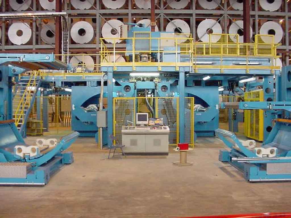
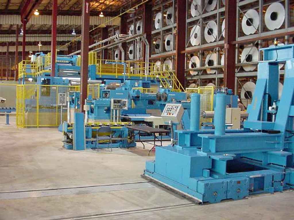
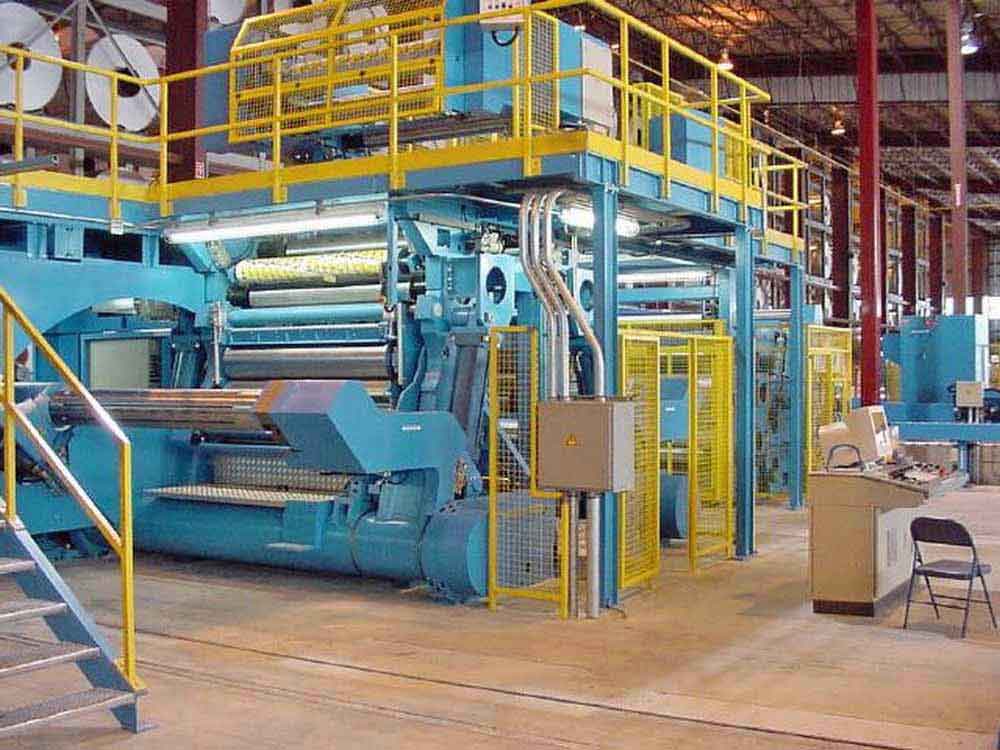
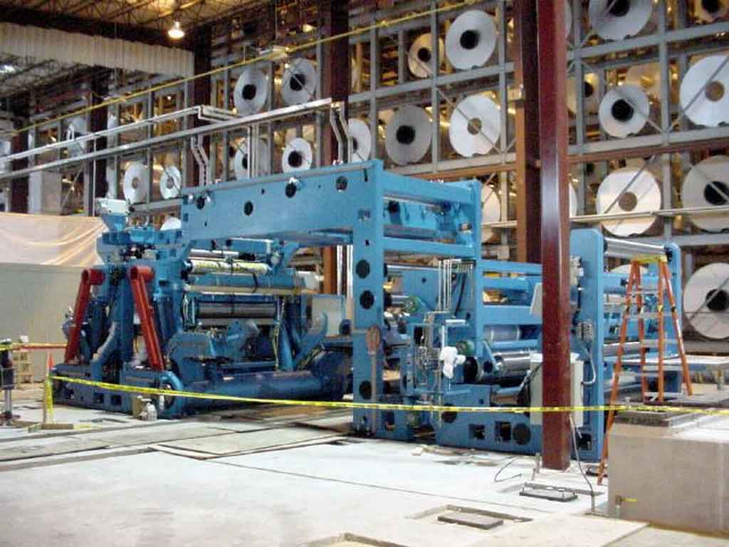
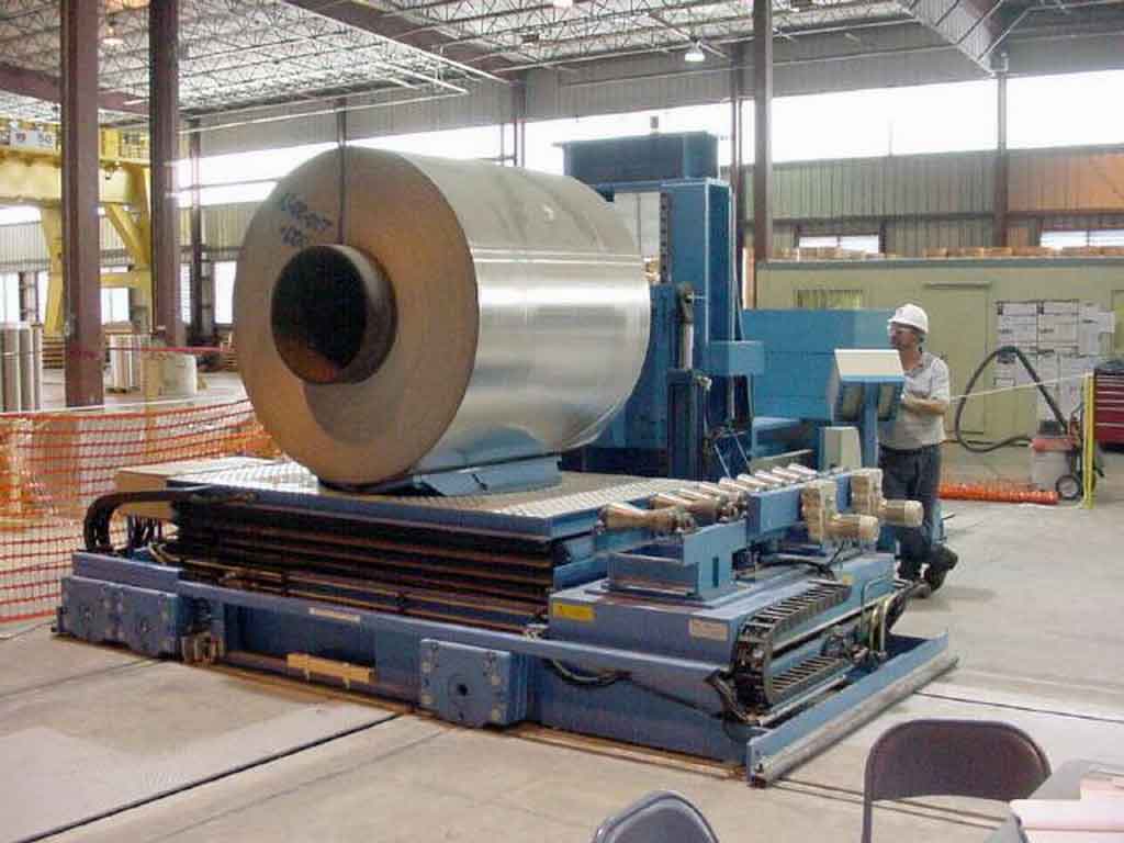
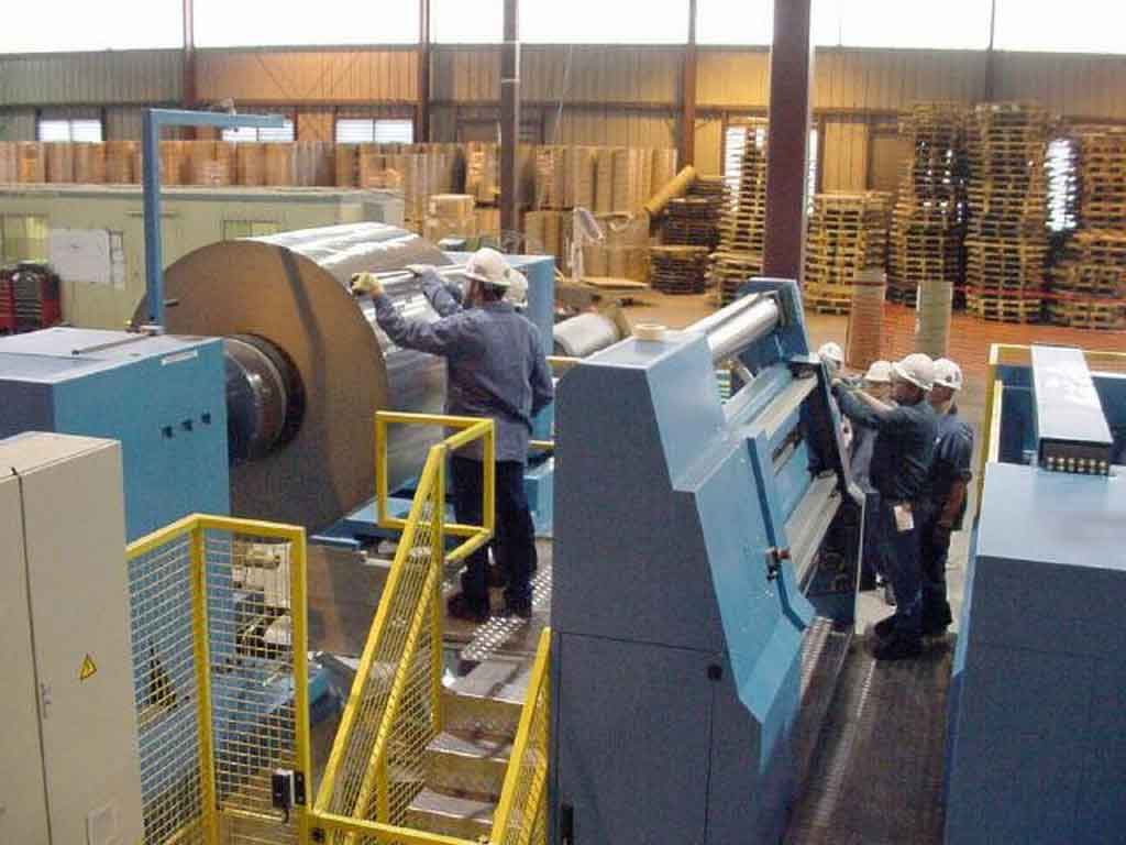
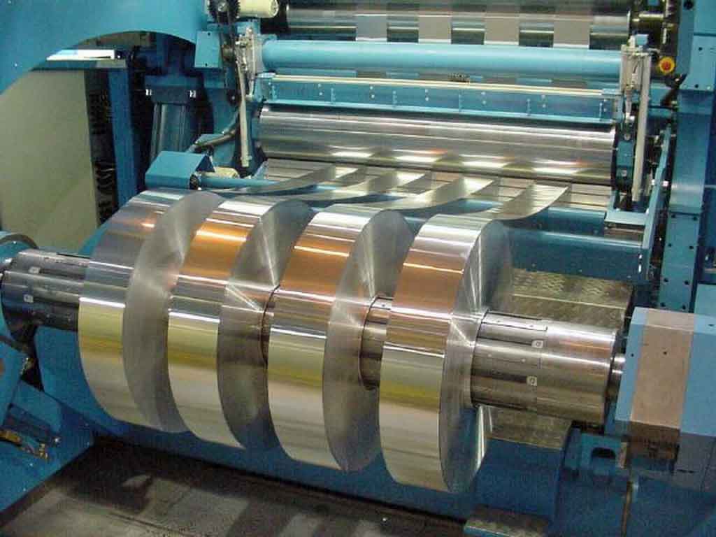
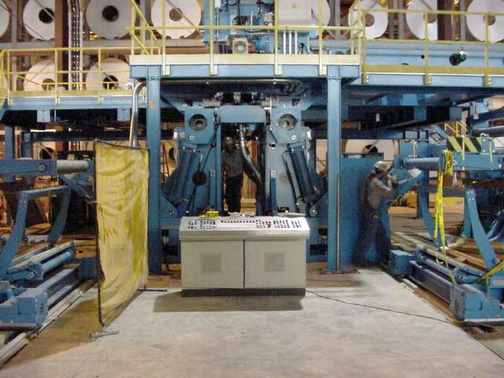
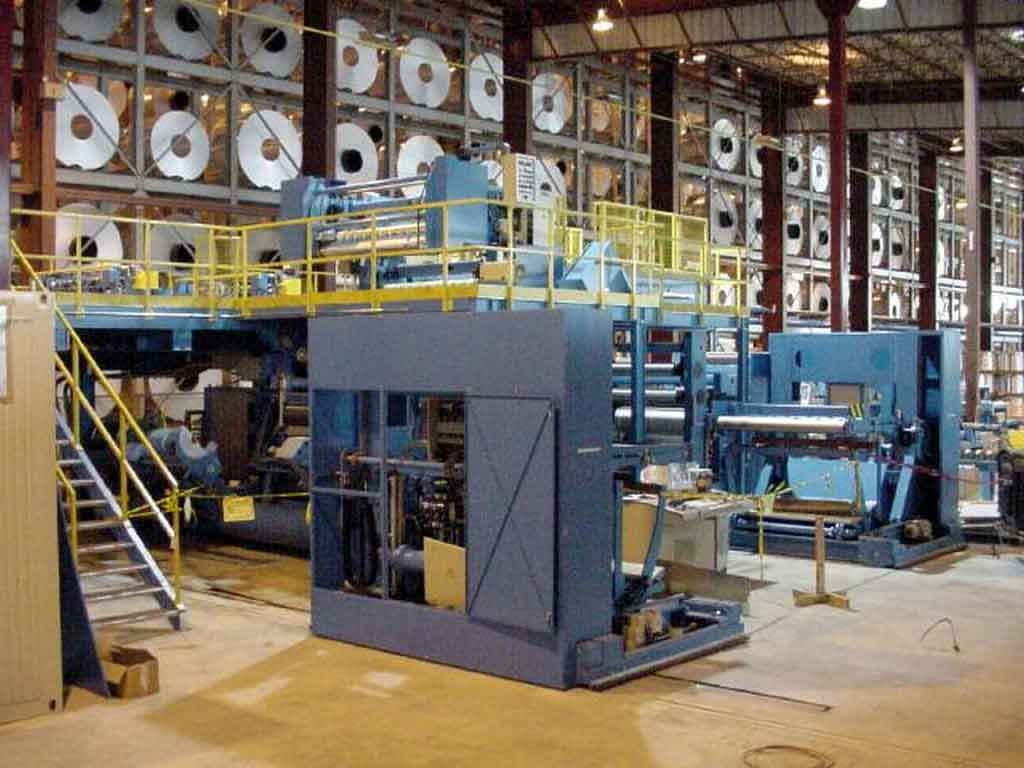
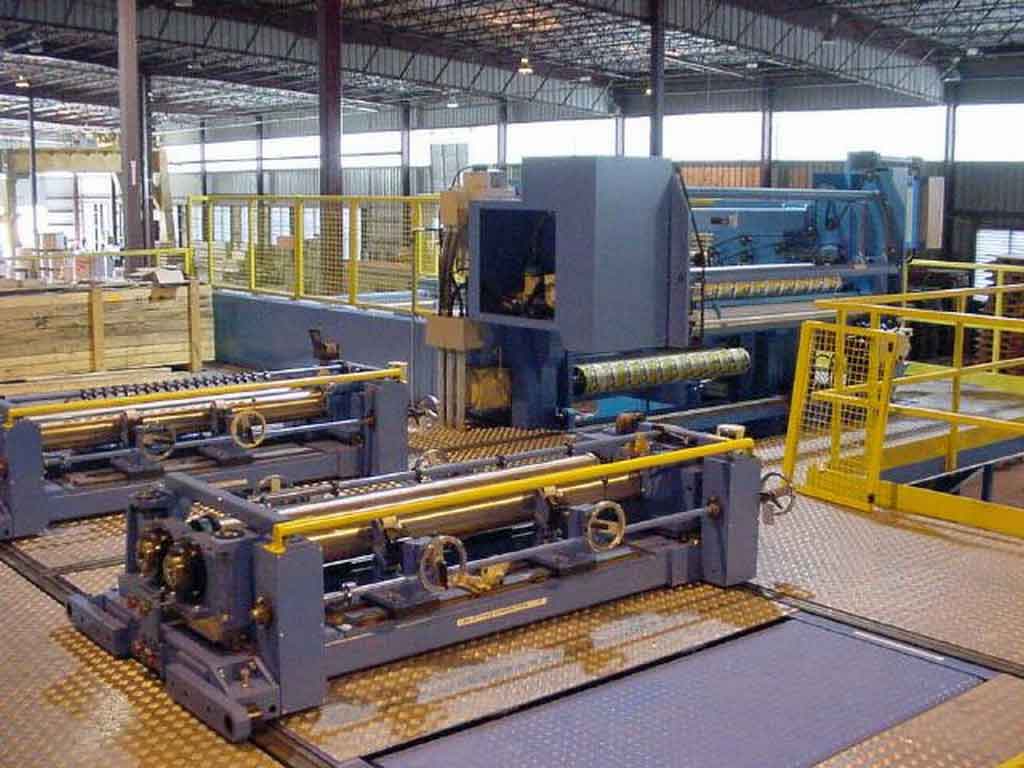
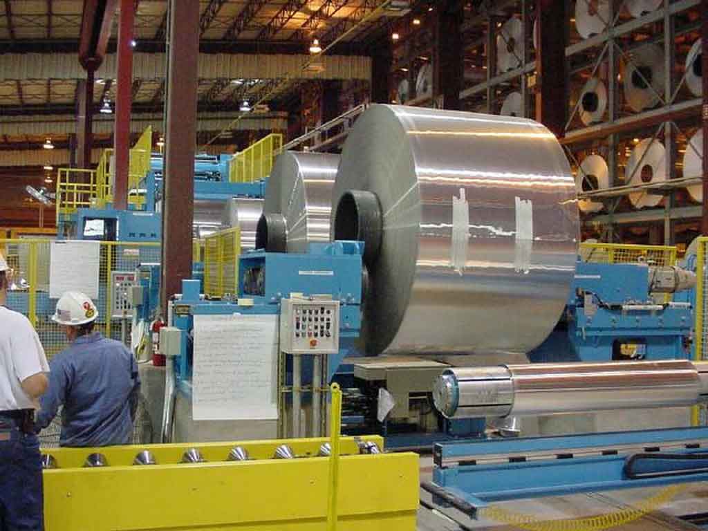
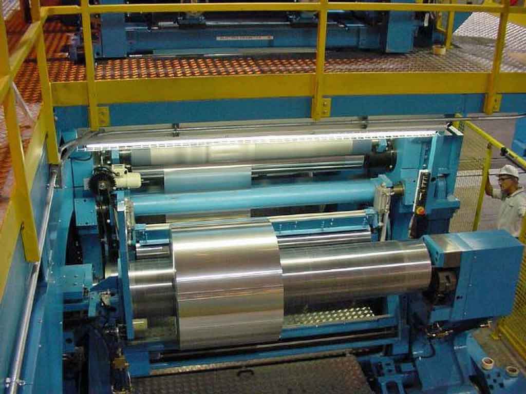
YEAR: 2001 72" x 0.002" - 0.015" x 40,000 Lb. Kampf Aluminum Slitting Line Material Processed: Alum. Alloys; 1145, 1100, 3003, 7072 and 8111 Temper: 0 Thru H19 Entry Strip Width Range untrimmed: 25" - 72" (635 - 1830 mm) (See Note at Slitter) Strip Thickness Range: 0.002" - 0.015" (0.051 - 0.381 mm) Line Speed: 2600 Ft/min. Maximum (800 M/min.) Depending on material type, thickness, Spool, Core and slitting width. Slitting Width Range: 0.6" - 46" (15.8 mm - 1169 mm) Maximum 40 Cuts Plus Edge Trim Exit Reels Diameter O.D. Max.: 72" (1829 mm) O.D. Min.: 18" (457 mm) (Depending On Material Type, Thickness, Spool, Core and Slitting Width) Spool/Core I.D.: 6", 10", 12", 16", 20" Dia. (152, 254, 304, 406, 508 mm) Fiber Cores (Cardboard) Slitting System: Scissors Cut / Optional square knife Edge Trim Min./Max.: 0.5" - 2.0" Per Side (12.7 - 50.8 mm Per Side) Slit Width Tolerance: +/- 0.004" (0.1 mm) Jogging Speed Approx.: 10 M/Min. (Adjustable) Acceleration/Deceleration: Vo - V Max. in approx. 80 S Instantaneous Stop: V Max - Vo in approx. 40 S Emergency Stop: V Max - Vo in approx. 10 S Winding Tension/Unwind: Max. 12.650 N Winding Tension/Rewind 1: 318 - 6328 N/25% Taper Tension at Outer Dia. Winding Tension/Rewind 2: 318 - 8438 N/25% Taper Tension at Outer Dia. Consisting of the Following: Unwind Coil Car: The car advances the coil thru the scrap prep station and to the main unwind in either manual or automatic mode. V saddle is a turntable and rotates the coil up to 180 deg. Scrap rewinder: Coil prep rewind stand Pneumatic radial clamping with air wrench Pusher plate to eject coil onto Prep Butt Table Prep Butt Table: Table transports scrap butts away from the line for removal Hydraulic cylinder raises and lowers the table Hydraulic motor driven rollers to move the scrap butts Coil Magazine #1: Prep station unwind station holds the coil and allows it to unwind onto the scrap rewinder Spool sizes, 66 to 72" and TBD Drive motors move the mandrel to unwind the metal Coil Magazine #2 Coil holding stand to hold the coil until ready to slit Spool sizes, 66" to 72" and TBD Driven spool length compensator to adjust for spool length Main Unwind Reel: Fixed gear AC motor powered Electro pneumatic brakes, Inch Brake for maintaining web tension Servo Motor for maintaining web tension during slitter operation Hydraulic cylinder core length adjustment Chucks are graduated for different I.D.'s Ultrasonic coil tracking sensor Coil O.D. Max.: 90" (2286 mm) Coil O.D. Min.: 24" (610 mm) Spool Size I.D./O.D./Length: 23.75" x 26" x 72" (603 x 660 x 1829 mm) 12.812" x 16" x 66" (325 x 406 x 1676 mm) 12" x 16" x 27.50" (304,8 x 406 x 698,5 mm) Unwind and Coil Stands to be designed to accept future Spool length of 76" (1930,4 mm) Splice Table: The splice table allows operators access to the coil ends for threading and splicing. Idler rolls feed the metal thru the splice station; 3 idler rolls Splice platform provides personnel access to the station Clamping bars secure the metal; 3 pneumatic actuated clamping bars Automatic cross cutting device, motorized traverse Taping is done manually via 50mm wide 3" core tape spools Automatic Threading Bar: Leads the attached metal from the splice table thru the slitting Cassette. Threading chain pulls the threading bar back and forth thru the line. Butt Conveyor and Spool Storage: Carries spool or spool and butt away from the unwind stand. Roller table Lift out device Stretcher Rolls: Rolls secure, stretch, guide and apply tension to the metal thru the slitter Entry rolls adjust up and down on operators side 3 Nip rolls hold tension against the stretching rolls Transport rolls feed metal thru the slitter rolls, hold tension and adjust the wrap angle of the metal in the slitter; Rolls 3,4,6, and 8 are independently driven. Transports 1 and 2 drive 7 rolls each, control tension, 5 and 7 drive 2 rolls each, control tension. 3 Stretch rolls stretch and harden the metal through the slitter. Rolls have a special coating Stretcher rolls have incrementally smaller sizes as the metal progresses downstream; 3 graduated sizes for 1%, 2% or 3% stretch. Configured largest to smallest. 2 Clamping rolls prevent metal from springing back into zone 2, auto thread. 2 Exit rolls; one at each rewind 3 Contact measuring rolls use load cells to take pressure reading for tension calculations and absorb shock and supply backup force at the rewinds. 1 at the entry to zone 2, has 2 load cells; 1 at each rewind, pneumatically powered compensating rolls on dancer system. Texturing Roller Unit: To apply light coating of lubricating oil to heavy gauge aluminum foil prior to slitting the foil. The lubricant facilitates the manufacturing finished products from the foil. Electrostatic Oiler: 5 separate heated tanks supply different liquids or wax to the electro-static applicator bar. closed loop blade heating system Strip enters thru the bottom of the oiler enclosure 2 spray blades, one top and one bottom Blades can be set by means of air actuated valves to vary the width in 4" increments from 28" min to 72" max. Fluid reservoir 1600W immersion heater Tank Farm: Tank 1, lubricant XL-301 Tank 2, lubricant PL-1043 Tank 3, lubricant PL-1027 Each tank stand includes, Base 25 gal, 2 Batch 5 gal each used to mix lubricant with lecithin additive, Additive 5 gal stores lecithin. Slitting Cassette: Top knife shaft adjusts both horiz. and vert., secured jet nuts Top knife set, 2 holders, knife, snap ring, spring Bottom knife shaft, stationary, secured by jet nuts Bottom knife set, knife, rounded edge spacer 2 knife shaft support rollers on each arbor Felt knife pads, one for each knife Cross cutting device, automated, traverse by motor 2 heads, on injector set rails, manually operation Suction Unit: Transports scrap from the slitter to the baler. Adjustable pull rolls, transport 8 Adjustable shifting suction nozzles, 2 large and 2 small Pushers, close unused suction nozzles, 4 pushers Flexible metal hose for transport to bifurcated pipes which transport scrap strip to baller Scrap choppers: Chop scrap in the suction tubes, 4 total in line, 4 spare for rebuild Rewind Reels: 2 separate rewind reels, that accept spools, diameters below 2 separate non driven winding rolls contact metal for tight wraps Fully automatic cross cutting device Rewind shafts expand Both Rewinds are driven by independent AC Motors, each drive stand has 2 motors, one small and one large Quick change hydraulically chucked mandrel connections Winding Shafts: 2 Rewind Shafts - 6" 2 Rewind Shafts - 10" 2 Rewind Shafts - 12" 2 Rewind Shafts - 16" Rewind Coil Cars: 2 separate cars for each rewind stand Hydraulic lift Hydraulic motor travel Seesaw lay-on arm: pivots to rest on top of the coil Clamping arm: secures the end of the coil for transport Machine Design: Drive side on the right, as seen in material running direction. Power: Voltage: 480 Volts + 10%-20%, AC-3 Phase, 60 Cycle +/- 2% Control Voltage: 24 Volts Total Supply amount: approx. 700 Kva Power cabinet was powered up and all drives fired up 02-2023 PLC Program copy is available Air: Continuous Pressure: >/- 5,5 Bar (>/- 77 Psi) Consumption approx.: 24 Nm3/H Water: Flow: 1,5 M3/H (53 Cu Ft/H) Full Inspection Report available from Kampf listing condition of this line. Line was removed from service in 2020. Removed and in storage: Toledo, OH. |